Vector Field Properties and Settings
Settings for visualizing vector-based maps in 3D views, as well as basic information about the selected vector field, are available in the Data Properties and Settings panel, shown below.
Vector field properties and settings

The following information is available for the selected vector field.
|
|
Description |
|---|---|
|
Name |
Indicates the name of the selected vector field. |
|
Number of vertices |
Indicates the total number of vertices computed for the selected vector field. |
|
X size |
indicates the dimension of the selected vector field in the X axis. |
|
Y size |
indicates the dimension of the selected vector field in the Y axis. |
|
Z size |
indicates the dimension of the selected vector field in the Z axis. |
The following settings are available for adjusting the visualization of the selected vector field.
|
|
Description |
|---|---|
|
Show arrow head |
If selected, arrow heads will appear on each vector in the field. |
|
Use direction as color |
If selected, each Euclidean vector will be colored according to its orientation — X in red, Y in green, and Z in blue. If not selected, each Euclidean vector will be colored according to the anisotropy value computed in the output anisotropy dataset. Coloring is selectable in the LUT drop-down menu. |
|
Length slider |
Lets you adjust the length of the Euclidean vectors in the selected vector field. |
|
LUT |
Lets you select the colors that will be applied to mapped anisotropy values. NOTE This option is not available whenever the Use direction as color option is selected. |
|
Range |
Lets you threshold the minimum and maximum values that are displayed. |
Vector fields can be examined in 3D views
- Select a 3D view in the workspace.
- Select the required vector field in the Data Properties and Settings panel.
Information and settings related to the selected vector field appear below the listed items in the Data Properties and Settings panel.
- Make the vector field visible by clicking the Eye icon.
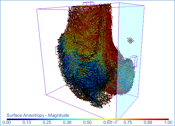
The vector field appears in the 3D view at the default settings, in which each vector is colored according to the degree of anisotropy values computed in the output dataset.
- Adjust the settings in the Vector field settings box, as required.
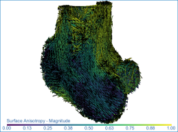
- You can uncheck the Show arrow head option to improve the visibility of the vectors in the field.
- You can adjust the length of the vectors, as well as select a different color mapping scheme in the LUT drop-down menu.
- You can threshold the minimum and maximum values that are displayed with the Range sliders or by entered new values in the Min and Max range boxes.
- You can color each vector according to its orientation by checking the Use direction as color option. If this option is selected, vectors oriented in the X axis will be colored red, vectors oriented in the Y axis will be colored green, and those oriented in the Z axis will be colored blue.
Note See 3D Scene's View Properties for information about adjusting the properties of the 3D scene view.
-
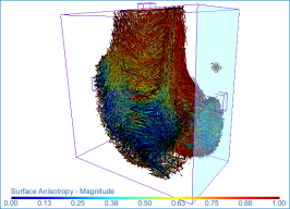
Apply clipping, if required, to clip interactively along orthogonal and oblique planes in 3D views of the vector field (see Clipping). You should note that clipping is applied by default to vector fields. Do the following to clip a vector field
-
- Click the Clip
 tool on the Clip panel that appears on the Data Properties and Setting panel.
 - Drag a face of the Clip box to move a plane up and down or in and out. Each plane of the 6 sides of the parallelogram can be moved independently.
- Drag any of the control points to rotate a side of the parallelogram.
- Translate the Clip box by dragging from the central control point.
- Click the Clip